Jump to content
Do Not Sell My Personal Information


  • Join Toyota Owners Club

    Join Europe's Largest Toyota Community! It's FREE!


General Information


Bibbs
 Share

Recommended Posts

BOV PROBLEMS on Rev1/2s

Some details from Chris Wilson @ http://www.formula3.freeserve.co.uk

He knows his stuff - building his own race cars etc.

In case folks are wondering WHY this is so, I feel I should re post the article I drafted when I was experimenting with my Skyline set up, the priciple of which holds good for all air flow metered turbo engines one may be tempted to fit a vent to atmosphere BOV to.

----------

For those sick of reading about my blow off valve saga, stop right now. For those who would learn from my mistakes read on ;-) To those that proffered advice, sincere thanks, it's been an interesting learning curve.

The following is based on my Skyline experience, with air usage measured by air flow meters before the turbos. It is not applicable to cars that soley use a MAP sensor and throttle angle for air measurement. To recap I put in a bigger intercooler and the standard Skyline duct that runs across the lower front of the car taking dumped air from the 2 blow off valves to the intake between the air flow meters and the twin turbo inlets was masking air exiting the lower 4 rows of the new IC.

Having spent a good deal of money on this item it pained me to see some of effectively blanked off. So I decided to blank the inlet off altogether where the cross pipe entered the turbo inlet ducting, remove the cross pipe and vent to atmosphere. The dump valves were being held open at idle by the idle vacuum level, so after ages of pondering i made a set up of solenoids to control  when vacuum was applied to the dump valves. This set up worked perfectly. *HOWEVER* a much more serious problem occurred, which any similarly inducted turbo car will potentially suffer if the boost air is dumped to atmosphere rather than as standard into the air intakes after the AFM (s). On the overrun, after a period of boost running, the standard set up will recirculate the excess boost back into the turbos, through the IC, and back through the dump valves to the turbo inlet again until the turbos inertia has slowed them to the point of little or no boost. The AFM's do not see any more air entering the engine, as it is being recirculated.

However, when we dump to atmosphere, that air is lost from the system and the turbos draw in fresh air via the AFM (s). This causes the engine to go mad rich, as the throttles are closed and no fuel is really needed. Hence the black smoke seen on the overrun after my mods.

Worse still was a noticeable but very short period of detonation when coming hard back on the throttle. This puzzled me totally, then it dawned. As the fuel system started working normally again the Lambda sensor "caught up" with what was happening, saw a very overly rich mixture, and shut down the injector pulse width, creating a very lean mixture, causing a brief, but very dangerous period of detonation!

I spent the afternoon and evening making new bracketry for the IC, new hoses and adaptors and shifting the IC forward that critical 40 mm or so, enabling me to fit the original moulded duct from the BOV's behind the IC without blocking it. Quite a lot of work and fabrication...

However, the mod I was planning could well have caused damage, and is certainly something to be very aware of if one has a similar AFM pre turbo set up changed to dump boost to atmosphere. The type of BOV matters not, it's the fact that the air no longer re circulates but is lost from the system, confusing the AFM (s) into thinking the engine is wanting more air/fuel mixture. An oscilloscope on the O2 sensors confirmed what was happening. We live and learn, often the hard way, but in this case not as hard a lesson as it might have been. I hope this helps, I searched the web long and hard for references to BOV problems, and failed to find any details of why dumping to atmosphere on none MAP sensor systems, that aren't mapped for this, is potentially dangerous.

Link to comment
Share on other sites

  • 3 months later...

AIR FILTER test

Blits, HKS, A'pexi & K&N

Test on a 300ps Supra

Page1

Page2

Link to comment
Share on other sites

HOW DOES A DYNO WORK

With thanks to Dave Baker @ Puma Race Engines

www.pumaracing.co.uk

There are more interesting articles on their site.

MEASURING ENGINE POWER

There is in fact no way of directly measuring power - all types of dynamometer measure torque and then power is calculated from the formula we saw in the previous articles - BHP = Torque (ft/lbs) x rpm/5252. This basic equation is the cornerstone of all engine design and development work. Two main methods of measuring power are used in the automotive industry - (1) measurement at the crankshaft of the engine or (2) measurement at the driving wheels. We'll look at both of these separately.

ENGINE DYNAMOMETERS

If we want to know the power of the engine alone then an engine dynamometer (or dyno) is used. This is how nearly all manufacturers rate the output of car engines. The engine is bolted into a cradle and connected to the dyno with a prop shaft which bolts onto the back of the crankshaft (or the flywheel). The power figures measured in this way are therefore usually called "flywheel power". The dyno is essentially a "brake" which can apply a known torque (or "load") to the engine. When the engine is holding a steady speed under a given dyno load then the torque being applied by the dyno must be exactly equal to the torque being produced by the engine. If this were not so then the engine would either accelerate or decelerate. Let's say we want to know the engine torque at full throttle at 3,000 rpm. The throttle is gradually opened and at the same time the load applied by the dyno is increased - eventually by juggling the amount of load applied we get to the situation where the throttle is fully open and the rpm is steady at 3,000. The torque being applied is written down and then the operation would be repeated at say 4,000 rpm. Soon we get a complete chart of torque at all engine speeds. Of course we could also measure part throttle power if desired.

Modern dynos are computer controlled and can generate power and torque curves very rapidly without the operator having to manually adjust throttle and load controls. They can be programmed to measure every so many rpm, say in 250 or 500 rpm steps - or they can measure a continuous torque curve while the engine accelerates at a preset rate. This can be used to simulate how the engine would actually operate in a particular gear when installed in the car.

There are various ways in which the dyno load can be applied. Older dynos use a hydraulic system with a rotor inside a water filled cavity - rather similar to the torque convertor in an automatic gearbox. Modern dynos generate the load with large electric motors. Even a simple friction disk or drum brake will work fine and this is where the name "brake" in Brake Horsepower came from. The important thing is that the load is able to be measured accurately and that there are no frictional losses in the system that escape measurement.

In order for dyno results to be comparable and universally understood there are a number of things that need to be closely controlled during the measurement process:

Operating Conditions

Air temperature, pressure and humidity affect the amount of power an engine produces. Cold dense air means a greater mass of oxygen per power cycle and thus more power is generated (provided of course that air/fuel mixture is properly calibrated for the conditions prevailing). There are formulae that can be used to calculate how much the measured power would change if the test conditions were different. This enables dyno results to be "corrected" back to standard conditions to enable comparison with anyone else's test results. Sadly however there is no one universally accepted set of "standard" conditions because different automotive bodies in different countries use different standards to calibrate to. "SAE" power standards are used in the USA and sometimes in England. "DIN" standards are used on the continent and there are a few other oddball systems just to confuse the issue. So just because your car is rated at 100 bhp and a friends at 110 bhp doesn't necessarily mean that his engine is more

powerful - it depends whether both measurements were corrected to the same standard conditions.

One of the tricks I've seen used to get bigger "corrected" bhp numbers is to use a very high ambient temperature reading for the dyno test. If the operator measures the temperature close to the engine rather than well away from it then obviously he will get a reading that is much higher than ambient. When the bhp numbers are corrected back to a lower standard ambient temperature they will increase. I saw an engine dyno sheet the other day where the ambient air temperature in February, in England was supposedly 37 degrees C. Now either that test was done with the temperature probe sat right on top of the engine or it's a part of country I don't yet know about where I would very much like to live !!

Engine Ancillaries

When installed in the car, the engine has to drive a number of items like the alternator and power steering pump which sap power. Also the exhaust and air filter systems will reduce power to some extent. If the engine is tested without any of these ancillaries fitted then it will show much higher power figures. The Americans used to rate their engines like this back in the fifties and sixties and often the installed power of the engine would only be 2/3 of the claimed figure in the sales blurb. This used to be called "gross" flywheel power and if the ancillaries were fitted the power was called "net" flywheel power. Nowadays the gross system, which was very misleading, is not used and all modern published data should be "net flywheel" power. Major manufacturers abide by rigorous standards which set out how the engine should be installed on the dyno to simulate closely the "in car" conditions.

ROLLING ROAD DYNAMOMETERS

Also called chassis dynamometers, these are used to measure power at the driving wheels. This avoids the inconvenience of having to remove the engine to test it if a tuning modification has been made. However, it means that the power figures obtained will be lower than the flywheel power because of the frictional losses in the drivetrain and tyres. This leads to one of the biggest sources of confusion, error and plain misinformation in the tuning industry. You see, as discussed above, all major manufacturers quote flywheel power so it is understandable that people want to know if the hard earned cash they spent on tuning mods increased the power of their engine and by how much. To know this for certain means knowing how much the transmission losses are. There is enormous pressure on rolling road operators to be able to quote flywheel bhp rather than wheel bhp and most operators now run proprietary software systems which "supposedly" print out flywheel power.

PROBLEM !! - THESE SOFTWARE SYSTEMS DO NOT AND CANNOT WORK !!

Yes - I know - the whole chassis dyno tuning industry quotes flywheel figures and here's me saying none of it works. So I'd better explain some more and then you can make your own mind up.

First, let's look at how a chassis dyno works. The car is driven onto a rig so that the driving tyres are resting between two steel rollers. The torque is measured at different speeds in exactly the same way as an engine dyno works except that it is torque at the rollers rather than torque at the flywheel. The braking load is applied to one of the rollers by either a hydraulic (water brake) or electrical system again in just the same way as the engine dyno would apply a torque to the crankshaft of the engine. The same universal equation at the top of the page can then be used to calculate bhp at the rollers by knowing the torque and the rpm of the rollers (NOT the rpm of the engine at this stage) - but if the engine rpm is measured simultaneously then we can know roller bhp at a particular engine rpm. The BIG problem with all this is if any tyre slip is taking place. Remember these are

smooth steel rollers which over time get quite polished. How much grip do you think you would get if roads were made of polished steel rather than tarmac? The effects of tyre slip are complex (i.e. I don't pretend to fully understand them myself!) but what I do know is that you can get some really strange bhp figures from highly tuned engines on narrow tyres and the readings are invariably too high not too low.

What is a transmission loss ? Well all mechanical systems suffer from friction and a proportion of the power fed into a system will get dissipated by friction and turn into heat and noise. Note the key phrase there - "power fed into a system". For there to be a loss there must be an input - simple and obvious yes but we'll see the relevance in a minute. When your car is parked overnight with the engine switched off, the transmission losses are obviously zero. When the car is running then some proportion of the flywheel power will be lost in the gearbox, final drive, drive shaft bearings, wheel bearings and tyres. For a given mechanical system these losses will usually stay close to a particular fixed %, let's say 10% for arguments sake, of the input power. So if the car is cruising and developing 20 bhp then 2 bhp will get absorbed as friction - under full power, say 100 bhp, then maybe 10 bhp will get absorbed. Now it is true that not every component in a transmission system absorbs a fixed % of the input power. Some components like oil seals and non driven meshed gears (as in a normal car multi speed gearbox) have frictional losses which are not affected by the input torque. These losses do increase with speed of course but at a given rpm can be taken to remain constant even if the engine is tuned to give more power. We'll look at real world transmission loss percentages later. Finally, the biggest source of loss in the entire transmission system of a car is in the tyres - they account for half or more of the total losses between the flywheel and the rollers. Each set of driven gears, i.e. the final drive gear or the particular gearbox ratio that you happen to be testing the car in, only absorbs about 1% to 2% of the engine's power.

Ok - so how do these software systems that supposedly measure transmission losses so as to "predict" back to the flywheel bhp work. The power curve at the wheels is taken in the usual way as explained above. Then, at peak rpm, the operator puts the car into neutral and lets the rollers slow down under the drag of the tyres and transmission. The software then measures this drag (or "coast down loss") as "negative" power and adds it to the wheel power to get back to the supposed flywheel power. BUT - and hopefully you've all spotted the problem now - the engine is not feeding any power into the drivetrain while the car is in neutral - in fact it isn't even connected to the drivetrain any more!! Whatever drag this is that's being measured it has nothing at all to do with the proportion of the flywheel power that gets lost as friction when the engine is powering the car in the normal way. The engine could now be an 800 bhp F1 engine or a 30 bhp mini engine for all it matters because it isn't connected to the gearbox or feeding any power into it. Obviously this "coast down loss" is something to do with the transmission and tyres but it is not the true transmission loss - in fact this coast down loss should never be expected to change for a given car at a particular rpm regardless of how much you tune the engine whereas a true transmission loss will increase as the engine power increases because it is dependent to a large extent on the amount of power being fed into the transmission. I've seen a car that over time was tuned from 90 bhp at the wheels to 125 bhp at the wheels and the "coast down loss" stayed the same for every power run to within a fraction of a horsepower - exactly as you would have predicted. As the engine was tuned to give more power the "true" transmission losses must have also increased to some extent but these chassis dyno systems don't, and can't, show this happening.

So is there any way of really measuring the true transmission loss of a car? Yes - only one - by measuring the flywheel power on an accurate engine dyno, the wheel power on an accurate chassis dyno and taking one away from the other. There is no way on God's green earth of finding out the true transmission loss just by measuring the power at the wheels.

So hopefully that's got you all thinking a bit more now instead of just taking for granted the "flywheel" figure you were given last time you took your car to the rollers. Even worse is the fact that some of these software systems allow the operator to just programme in the % transmission loss he wants the system to add to the wheel figures. So if that isn't a nice easy way to show some big fat flywheel bhp then I don't know of a better one. It's certainly a lot easier than actually doing some proper development work to make the engine perform better - just dial in a bigger transmission loss and bingo - the same wheel bhp now turns into a bigger flywheel bhp - happy customer, happy dyno man - just a shame it was all sleight of hand. See the end of this article if you doubt that this sort of thing really happens.

So what should you do when you take your car to a rolling road? Firstly, make sure you get printouts that show the wheel bhp and not just the flywheel bhp. Then at least you can see if they look sensible in comparison. If you have a desperate need to know the flywheel bhp then you will have to estimate it - there's no other way short of using an engine dyno. The corrections you need to make for cars with manual gearboxes are these:

The average front wheel drive road car with between 100 and 200 bhp loses about 15% of the engine bhp as transmission losses.

The average rear wheel drive road car with between 100 and 200 bhp loses about 17% of the engine bhp as transmission losses. The increase in % loss over front wheel drive is because the differential has to turn the drive through 90 degrees at the back axle which soaks up a bit more of the engine's power.

4wd cars will have higher losses because of the extra differentials and other power transmission components. A reasonable estimate of an average 4wd car's losses might be 22% to 25% of the flywheel power but it isn't a subject I have sufficient data on to be definitive.

What your own specific car loses is anyone's guess - yours is as good as mine - but it shouldn't be far from the figures above. For sure though, no car in the world, unless it has flat tyres and a gearbox full of sand, loses anything like 30% of the engine's power in the transmission and tyres as many rolling road operators would try to have you believe. So take the wheel figure and divide by 0.85 for FWD or 0.83 for RWD and that will get you as close to the true engine bhp as you are ever going to know. In general though it is fair to say that low powered cars have higher % losses than high powered cars. For example, a 60 bhp Fiesta will have around 14 to 15 bhp total transmission and tyre loss whereas a 90 bhp XR2 will only have about 17 to 18 bhp loss - a smaller % obviously. By the time you get to RWD cars with engines in the 300 to 500+ bhp range, losses can eventually drop to as little as 12 to 14% or so.

Another rule of thumb I use which is quite accurate is to treat the losses as being 10% of the flywheel power plus 10 bhp for FWD and 12% plus 10 bhp for RWD cars. This equation "loads" low powered cars more than high powered cars which is more closely like what happens in reality.

Remember, these percentages are not "gospel" - they are good realistic averages. The measured wheel bhp can change depending on tyre pressure, tyre size, suspension angles and other things which won't affect flywheel power - so the actual transmission loss % will also change. It pays to try and standardize as many of these things as possible if you intend to do a series of power runs over a period of time. Always use the same tyre pressure because this is a factor which can easily change from day to day.

Some time ago I had three almost identical race cars set up together in a group session at a rolling road. The engines were very similar except for minor differences in the camshafts fitted. One showed 118 bhp at the wheels, another showed 124 and the third showed only 98. The operator spent ages I'm told (I wasn't there) trying to find why the third car was so poor. It wasn't till the next day when that particular owner was checking things before the race that he noticed that the tyres only had 7 psi in them - the car had sat unchecked over the winter and no-one had bothered to standardize the pressures before the dyno test. In the race, that car went just as well as the other two and if anything was slightly the fastest of the three. That gives you some idea of how much power a set of flat tyres can absorb.

As you tune a particular car, the losses won't increase exactly in proportion to the power because as mentioned above, some components in the transmission have fixed losses which are not dependent on engine power. However, neither you nor the dyno operator will have any real idea of exactly how the losses have changed so you might as well just continue to apply the percentages above to give some sort of realistic guide to the new flywheel bhp.

What sort of % transmission loss do these software systems show? - well for normal road cars in the 100 to 200 bhp category, I've seen as high as 35% and as low as 10%. So take the same car with 100 bhp at the wheels to 2 different rollers and you might get anything from 110 bhp to 140 bhp being "predicted" as the flywheel figure. In reality 100 bhp at the wheels will be no more than about 120 bhp at the flywheel. If being told a bigger figure makes you happy then good for you - the car won't go any faster and you'll be no nearer to knowing whether you really got more power out of it than standard.

Another good way of bumping up the power figures on rolling road tests, as mentioned above under engine dynos, is by "playing about" with the air temperature and pressure corrections . If you dial in your own "standard" conditions as being freezing cold with the barometer going off the scale, or you put the temperature probe near the engine, you can get the system to add huge amounts of power to what was actually measured. So make sure you know if such corrections were made or not and to what standards they were made if any. Plenty of rollers still just quote the measured figure because they don't have computer systems to do the calculations.

Hopefully it should be apparent that 100 bhp is not just 100 bhp and end of story. It depends how it was measured, where it was measured, what corrections were applied and of course whether the dyno was even accurate in the first place. So I don't get too excited anymore when I see other people quote huge power outputs for their engine mods. If my engines still beat their ones on the track then they can quote whatever power figure they like. As the saying goes - "when the flag drops, the bull***** stops".

Finally, the best rolling road con I've heard of to date is from a friend (before I knew him I hasten to add) who took his VW Passat to a well known VW specialist in the Oxford area for one of their proprietary "air box mods" which they said would give an extra 10 bhp. Sure enough he came away with a lighter wallet and a printout which showed 10 bhp more at the flywheel. It wasn't until you examined the printout carefully though, that it became apparent that the power at the wheels had dropped from 125 to 120 but the "coast down losses" had gone up by 15 bhp to give a net 10 bhp extra "predicted power" at the flywheel. The car, he says, felt slightly slower, which of course it was - by 5 bhp and that's a poor way to spend your hard earned money. Exactly how they fiddled the rollers to show such a hugely increased "coast down loss" I'll leave you all to speculate on.

The moral of the story is clear - if you don't know the power at the wheels you don't know diddly-squat - so as the man in Hill St Blues used to say - "be careful out there folks".

Here's a very good article by a Canadian tuning company on dynos and transmission losses - SDS dyno article - their main tech page has lots of other good stuff too and you'll see a link to it back on my mainmenu page.

SUMMARY

The "coast down loss" which some rolling roads add to the measured wheel bhp is not an accurate estimate of real transmission and tyre losses and will not give a reliable measure of flywheel bhp except by coincidence in some cases.

Average real transmission losses are about 10% of the flywheel power plus 10bhp for FWD cars and 12% plus 10bhp for RWD cars. This equates to about 15% to 17% for cars of "average" power output.

VW technical also quote their cars as losing, on average, about 15% of the flywheel power in the transmission and tyres.

The chassis dyno division of Bosch UK also suggest 15% as being a realistic estimate of transmission losses.

Be wary of "correction" factors for temperature and pressure which are often used to "massage" measured bhp figures in an unrealistic way.

This article is the intellectual property and copyright of David Baker and Puma Race Engines. 

Link to comment
Share on other sites

  • 9 months later...

WHAT IS PCD AND OFFSET

Wheel Size

Two measurements, the Rim Diameter and the Rim Width, normally determine the wheel size.

Wheelsize.gif

Offset

The ‘Offset’ of a wheel measures the distance between the wheel centreline and the wheel mounting face and is measured in millimetres. It is extremely important that wheels of the correct offset are used in order to maintain the correct track of the vehicles.

Offset can be Positive or Negative and is best illustrated in the two diagrams on the left. Most Modern vehicles are front-wheel drive, and as such generally require positive offset wheels. The main exception to this rule is 4x4 vehicles, which often use negative offset wheels.

offsets.gif

Clearance

It is, of course, extremely important that the clearance Pitch Circle Diameterof both the vehicle body work and steering/suspension components are maintained. Failure to do so would most likely cause damage to both the tyre/wheel assembly as well as the body of the vehicles. Clearance is achieved by selecting a wheel of the correct size and type of tyre. Quality alloy wheel suppliers can give such information.

Pitch Circle Diameter (PCD)

The P.C.D. can be defined as the diameter (in millimetres) of an imaginary circle drawn through the centre of the stud holes on the wheel and/or the vehicle wheel hub.

When new wheels are required, it is essential that they have the correct P.C.D. for the vehicle concerned.

PCD.gif

Wheel Location on Hub

Motor vehicle manufacturers use a central location collar on the stub axle hub in order to accurately locate the wheel. The wheel collar diameter varies, depending on the make of vehicle.

Many replacement allow wheel manufacturers use an adapter (spigot ring) to vary the diameter of the locating hole. In this way, a particular wheel can, by changing the spigot ring, be used on a variety of vehicles.

The adapter/spigot ring arrangement is illustrated in the diagrams to the left.

As an example, TSW Spigot rings should always be fitted without he tapered edge facing the vehicle hub. This is to allow easy and accurate location of the ring onto the hub collar.

wheelhub.gif

Upstepping to High Performance

Legal and illegal wheel/tyre combinationsVehicle performance can be maximised by selecting a lower profile tyre and larger wheel diameter combination. Care must be taken to select the appropriate replacement wheel / tyre combination to avoid problems.

For example, it is a legal requirements that the tyre and wheel assemblies stay within the body of the car.

upsteeping.gif

The fitting of larger diameter replacement wheels is referred to as ‘up-stepping’. Up-stepping‘Plus One’ or ‘Plus Two’ denotes how much larger the wheel diameter is.

This approach of ‘up-stepping’ allows the tyre section width to be increased whilst maintaining the correct overall diameter. This allows the optimisation of cornering force and grip whilst maintaining the original gearing of the vehicle. One example of this is:

195/60 R 14

14 inch diameter

Original size

205/50 R 15

15 inch diameter

Plus One

205/45 R 16

16 inch diameter

Plus Two

205/40 R 17

17 inch diameter

Plus Three

All of the above have an overall rolling diameter which is within an acceptable tolerance.

lagerfitting.gif

Aspect Ratio

Aspect ratio is the ratio of section height to section width. It should be noted that in general, tyres with a lower section height (i.e. where the aspect ratio is lowered) have a higher cornering force and therefore improved performance-handling characteristics.

Aspectratio.gif

Cheers

KiwiMR2

MR2 91 - 99

PCD:

5 X 114

OFFSET:

35 - 42

BORE:

60.1

Dave  :thumbsup:

-Dudeone 21/12/2004

Link to comment
Share on other sites

Latest Deals

Toyota Official Store for genuine Toyota parts & accessories

Disclaimer: As the club is an eBay Partner, The club may be compensated if you make a purchase via eBay links

Guest
This topic is now closed to further replies.
 Share


  • Topics

  • Our picks

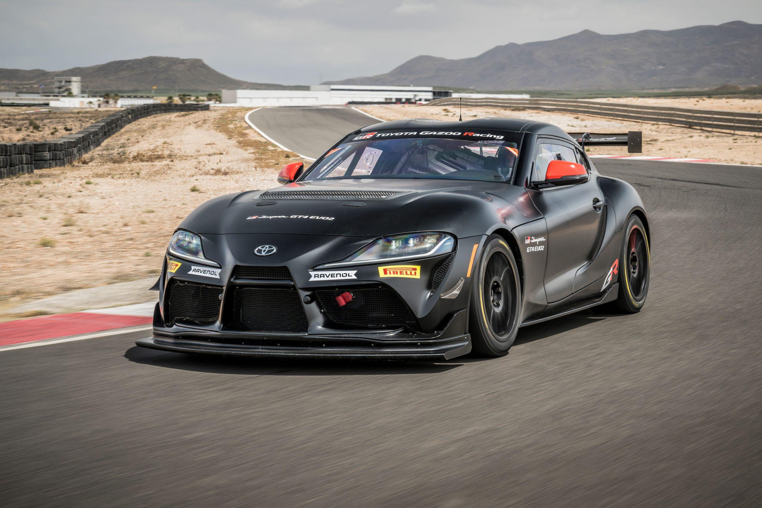
    • Toyota Gazoo Racing launches GR Supra GT EVO2 for the 2025 racing season
      Toyota Gazoo Racing (TGR) is now accepting orders for the new GR Supra GT4 EVO2. Vast feedback from racing teams and drivers around the world has been leveraged to produce an evolution of the GT car that delivers higher performance, reliability and operability.

      Since the launch of the GR Supra GT4 in 2020, more than 120 cars have been sold. The efforts of teams and drivers have seen it win GT4-series races and international events in 11 countries worldwide, gaining more than 500 podium finishes and becoming the class champion in Asia, the USA and Europe.
    • Going back to its origins: World premiere of the all-new Toyota Land Cruiser
      Toyota today proudly reveals the all-new Land Cruiser, a model that draws directly on the original qualities that have made the Land Cruiser name synonymous with strength and reliability for more than 70 years
    • Toyota Gazoo Racing prepares for historic centenary edition of the Le Mans 24 Hours
      Toyota Gazoo Racing will contribute to another chapter in the history of Le Mans when they take on a record Hypercar field in the centenary edition of the world’s most famous endurance race next week (10-11 June)
    • Toyota Prius honoured with lifetime achievement award
      The Toyota Prius’s status as the pioneer that paved the way for today’s electrified vehicle market has been recognised with a lifetime achievement award in the TopGear.com Electric Awards 2023
        • Like
    • Toyota Yaris reaches the landmark of 10 million global sales
      The ever-popular, multi-award-winning Yaris* nameplate has reached 10 million cumulative worldwide sales, performance which earns it a place alongside Toyota’s illustrious eight-figure achievers – Corolla, Camry, RAV4, Hilux and Land Cruiser
        • Thanks
        • Like

×
×
  • Create New...


Forums


News


Membership


  • Insurance
  • Support